Suitable for: Robotics 8452 Computer Control
The circuit described below is a simple and inexpensive 4-way input/output interface for the Centronics printer port. Final cost per interface is less than $200 with the power supply.
NOTE: You can now purchase the complete, assembled and tested interface, all cables and power supply AND site rights to use sample software written in Pascal and Logo AND a 50-page "How to" Robotics booklet on CD ROM and site rights to duplicate unlimited copies of the booklet for use at the site AND ongoing support from me all for $AUS150 per site!! (International customers email me for pricing: jfuller@southwest.com.au)
(Schools with an existing Site License for Robotics#3 can obtain a significant reduction in price. Give me a call.)
Output

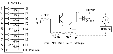
The output section is controlled by an eight line "Darlington Driver" integrated circuit (IC) called a ULN2803. The digital state of each of the eight lines from the printer port is used to control the IC's internal "drivers" which in turn control the Relays and LEDs. Power for the Relays and LEDs is provided by the 12 volt regulator (LM 7812) via a plug pack power supply of at least 15 volts and capable of supplying at least 1 amp. In this interface, each of the eight output lines at the printer port is connected via a 560ohm to a LED. Four of the output lines also have relays attached.
Software:
The code to control output is:
[outcommand][port address][output code]
where
[output code] = 1, 2, 4, 8, 16, 32, 64, or 128 and
[port address] may be 888, or 956 depending upon your hardware.
Examples:
Pascal - Port[888] := 4;
BASIC - OUT 888,32
WinLogo - OutportB 888 64 (Version 3.7 onwards)
Input
Each of the four input lines can detect the open/closed state of a switch. Each line is buffered using the 74LS244 IC. This IC provides a degree of protection for the computer, but it is VERY important that no current is connected to the inputs. Only switches may be used on the input lines!!
Software Input is read at the printer port using:
[incommand][port address]
Where:
[port address] is one higher than the corresponding output address for the printer port. ie 889, or 957
Examples:
Pascal - InValue := Port[889];
BASIC - InValue = IN 889,32
WinLogo - InportB 889 (Version 3.7 onwards)
NOTE: Once the value at the port has been read, you must use "ANDing" to determine which individual line is either HIGH, or LOW.
The "PCB mounted DB25 Socket" connects via a 'serial' cable to the printer port.
NOTE 1: The cable must be a male-male (plug-plug) type with 'straight through' connections. ie 1 to 1, 2 to 2, 3 to 3, etc. This type of cable is commonly used with printer switch boxes. (A "null modem" cable has lines 2 and 3 crossed and is not suitable - unless you make allowances in your programming.)
NOTE 2: The power supply for this interface can be either AC or DC as long as it can deliver at least 1 amp. The diode bridge makes connection fool proof. The power supply can be connected either way around.

Parts List
1 x 25 pin DB PCB mount female socket
8 x 3mm red LEDs
8 x 560ohm 1/4 watt resistors
4 x 100kohm 1/4 watt resistors
1 x 10kohm 1/4 watt resistor
1 x IC ULN 2803 8-way line driver
1 x IC 74LS244 octal buffer
1 x LM7805 regulator IC
1 x LM7812 regulator IC
1 x 1000uF electrolytic capacitor
2 x 0.01uF greencaps (approx)
1 x 1 amp diode bridge
1 x 2.1mm power socket
1 x PCB
4 x 3-way PCB connectors
4 x 2-way PCB connectors
4 x mini pushbuttons
4 x 12 volt SPDT relays
1.5m hookup wire
1 x 15 volt AC/DC 1 amp (minimum) plugpack power supply (2.1mm plug)
For more information contact:
jfullerEDUCATIONAL
48 Portmarnock Circle
MANDURAH WA 6210
Western Australia
or:
phone (A/H) 08 9535 6471
or email: jfuller@southwest.com.au